In a food manufacturer's packaging line, individual boxes are packed in outer boxes and labelled. Once the boxes are sealed, they must be transferred to automatic palletising. In order to be transferred, the boxes have to be elevated to a height of approx. 3.5 m.
Belt Conveyors with a Modular, Profile-Based Design
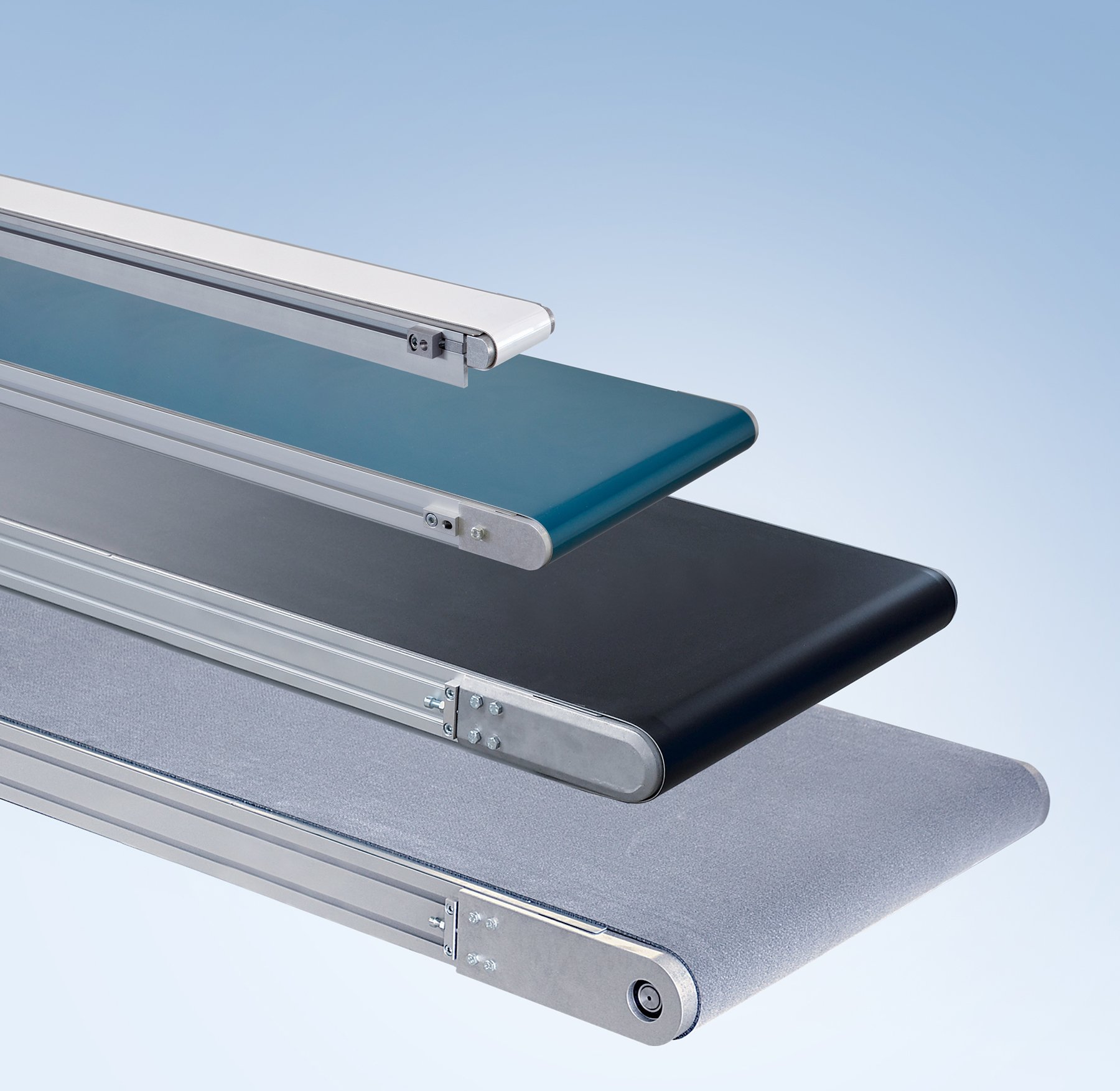
In nearly all industrial applications, belt conveyors handle the majority of material transport tasks. They are suitable for transporting both packaged and unpackaged piece goods with a wide range of shapes and dimensions.
Conveyor belts are the plant construction solution of choice for moving products to and from stations in processing lines. With their extensive range of standard modules and accessories, mk belt conveyors can be perfectly adapted to any requirements. In additional to straight conveyors, incline and curved belt conveyors are also available.
Technical Data depending on the system:
- Widths: 50-2000 mm
- Lengths: 300-20000 mm
- Total load: typically up to 200 kg
- Speed: up to 80 m/min
- Options: dual-line, incline, curved, INOX
*other values available on request
| Conveyor name | Conveyor- type | Conveyor- width [mm] | Conveyor- length [mm] | Total load as stand. up to [kg] | Speed up to [m/min] | ø of tails [mm] | Reverse operation | Accum. operation | Cycling operation |
|---|---|---|---|---|---|---|---|---|---|
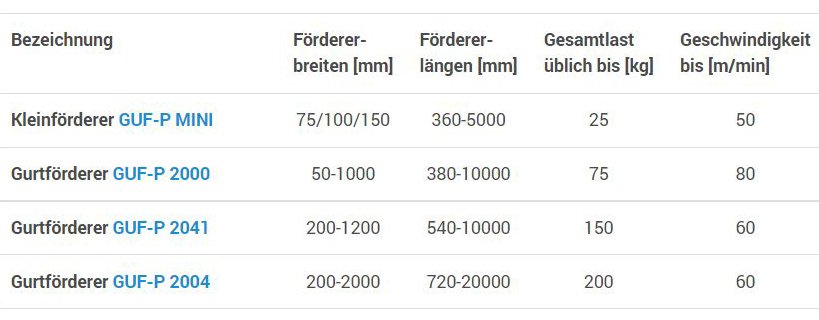
| Small conveyor GUF-P MINI | Straight | 75/100/150 | 360-5000 | 25 | 50 | 22/32 | X | X | X |
| Belt conveyor GUF-P 2000 | Straight | 50-1000 | 380-10000 | 75 | 80 | 10/12/19/53 | X | X | X |
| Belt conveyor GUF-P 2041 | Straight | 200-1200 | 540-10000 | 150 | 60 | 22/85 | X | X | X |
| Belt conveyor GUF-P 2004 | Straight | 200-2000 | 720-20000 | 200 | 60 | 105 | X | X | |
| Incline belt conveyor KFG-P 2000 | Incline | 300-700 | 1400-4000 | 40 | 15 | 53 | X | ||
| Curved belt conveyor KGF-P 2040 | Curve | 300-600 | 90°/180° | 30 | 30 | 19 | X | ||
| Dual belt conveyor DGF-P 2001 | Double | 100-250 | 300-2000 | 15 | 15 | 25 | X | X | |
Conveyor Technology Catalogue
Detailed information on belt conveyors can be found in our conveyor technology catalogue.
Download nowConfigurator Conveyor Technology
Our QuickDesigner lets you easily create a custom mk belt conveyor, along with the corresponding CAD model and quotation.
Configure NowExtremely sensitive products can be damaged simply by being placed on conveyor technology. This is true both for very light and fragile products as well as for heavy and vibration-sensitive products. A solution was needed to minimize the shock to the products when setting them down on the conveyor.
An automotive supplier for lighting technology and electronics requires further automation of its existing processes to keep its location competitive for the future. The customer wishes to improve the flow of materials at the injection moulding machines to allow for more efficient and flexible use…
FAQ Belt Conveyor – Questions and Answers Concerning the Belt Conveyor
This text contains the most important questions and answers concerning the belt conveyor. If you do not find the answer to your question, please do not hesitate to contact us. We’re happy to assist you personally as well! Contact your responsible contact partner on site or use our general contact form.
The belt conveyor is also referred to as a conveyor belt, ropebelt conveyor, transport belt, assembly belt, assembly conveyor or, colloquially, as an assembly line. At mk, we simply call it a GUF, which is short for "belt conveyor" in German.
The belt conveyor is especially well suited for transporting packaged and unpackaged piece goods that have different shapes and dimensions. It has no specific requirements regarding their position, orientation or product geometry. Additionally, it can be designed as a stationary or mobile conveyor system.
The belt conveyor's transport medium is a continuous, endless fabric band (conveyor belt) that is driven using a drive and idler pulley via frictional connections. In contrast, the transport medium for modular and flat top chain conveyors consists of linked chains. They are driven via a close fit but generate more noise than belt conveyors.
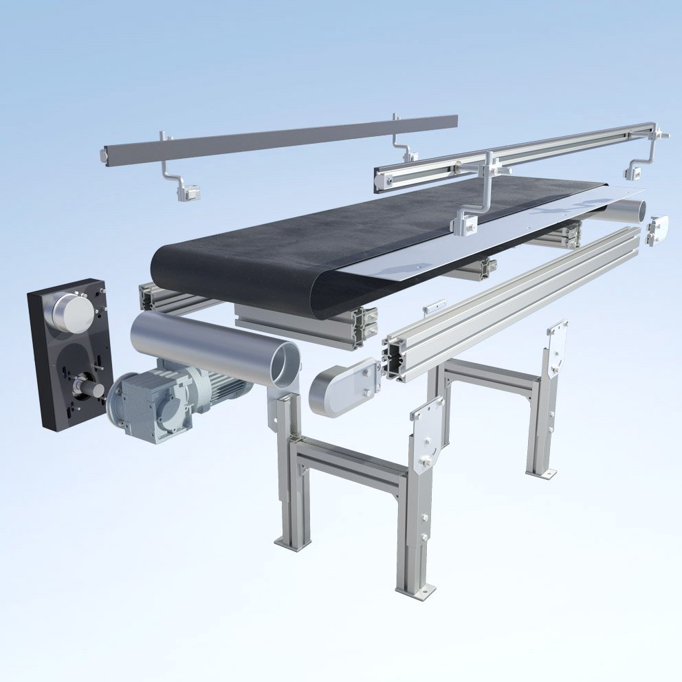
Belt conveyors essentially consist of the following:
- Conveyor body: supporting structure, for example made of aluminium profile
- Drive roller: steel roller with motor; driven directly, indirectly or internally
- Idler pulley: opposing steel roller
- Conveyor belt: endless belt driven by frictional locking
- Slide bed: harness support for moving support, for example made of stainless steel
- Various accessories: stand systems, side rails, control elements and much more
Belt conveyors are used in nearly all industrial applications when piece goods without specific requirements regarding their position, orientation or product geometry need to be transported. Products with different forms and dimensions, that are packaged and unpackaged, light or heavy can be transported. In addition to straight lines, routes along curves or to other levels can be realised.
Normally total loads of up to 200 kg and speeds of up to 80 m/min. are possible, depending on the conveyor's design. Examples of factors that can influence the conveyor's load include:
- The weight and dimensions of the product
- The route
- The conveyor width
- The roller diameter
- The belt type
- The pre-tension
- The load distribution, operation type and environmental conditions
Environmental conditions
When a conveyor is configured, typical environmental conditions in production are assumed. That means the application is indoors at temperatures between +10° and +60° C in a clean environment with a typical humidity of 30 to 60% and no condensation or dripping water. Depending on the belt material, however, temperatures of -30 to +150° C are possible.
Alternatives from mk
For transporting products containing oil or featuring sharp edges or for higher ambient temperatures, chemical resistance or humidity, a modular belt conveyor is better suited. Modular belts are more robust and, accordingly, more resistant to wear than other belts.
If the product contacts the transport medium at temperatures of up to 200° C, a conveyor system with a steel chain should be selected.
And if the product needs to be transported with a specific position and orientation, transport via pallets is recommended. Our pallet circulation system Versamove, our flat top chain conveyor system Versaflex, our accumulating roller system SPU-2040 and our cycled conveyor TKU-2040 are especially well suited for this purpose.
Like all of mk's conveyor systems, the belt conveyors are also constructed based on mk's own profile system. That means they are made of aluminium profiles with sturdy connection technology featuring standard screws. No welding, abrasive cutting or painting is necessary. On the one hand, the aluminium profile construction guarantees easy conveyor assembly and maximum flexibility during modifications. On the other, it ensures a torsion-resistant conveyor frame with very good carrying capacities.
An additional benefit of the profile construction is that all installations and systems from mk are compatible with one another. As a result, they can be optimally integrated into existing and complex systems. The standardised T-slot with a 10 mm slot width also guarantees integration into aluminium profile constructions from other manufacturers.
In addition, the T-slot features connection options for add-on components like stands, side rails, initiators, stoppers and other accessories on the two longitudinal sides of the conveyor frame.
Conveyor frame profiles
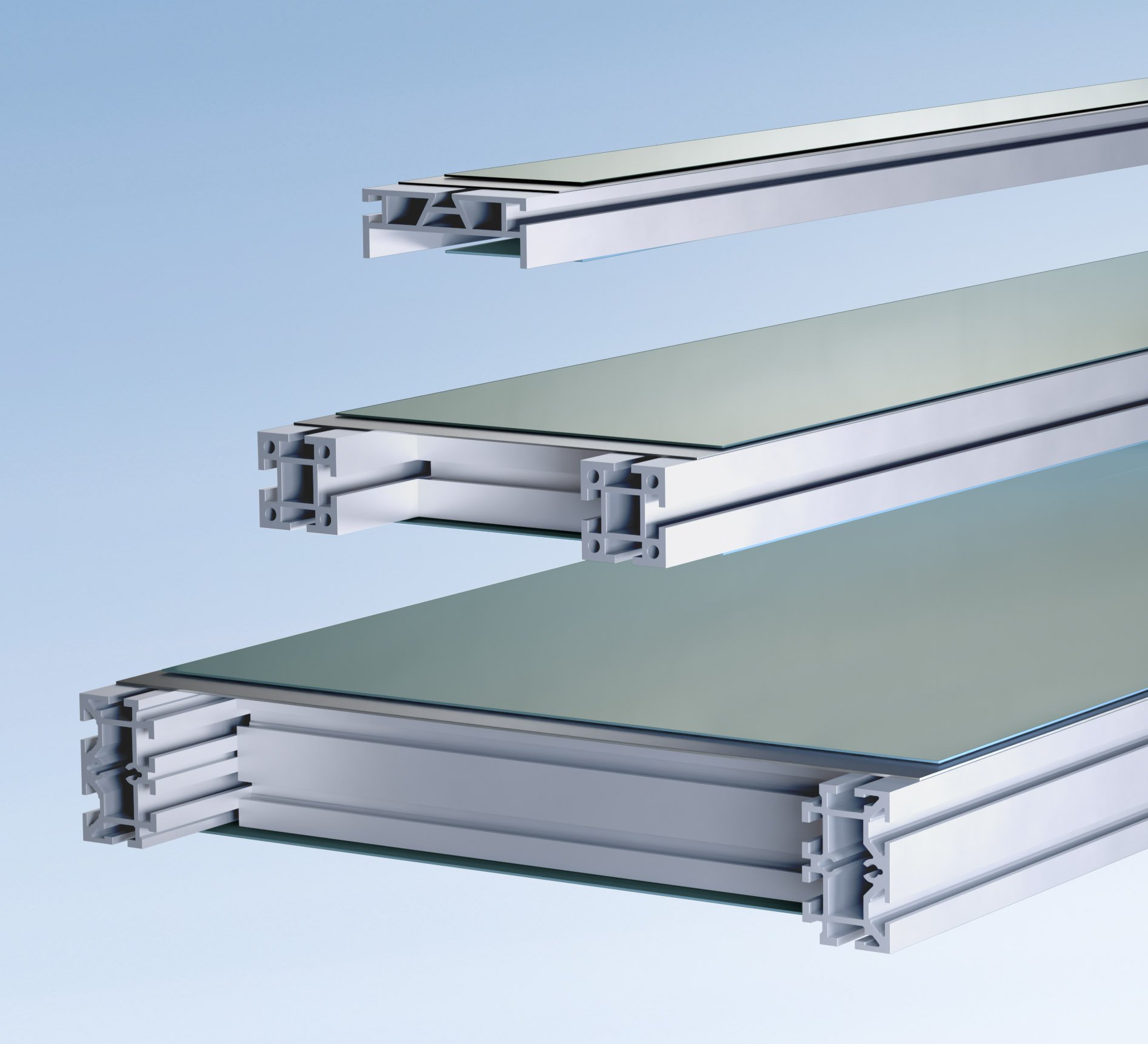
Conveyor frame profiles with a wide range of cross sections are available for a large number of requirements for constructing mk conveyor systems. For small belt conveyors, a profile can be used directly as a conveyor frame. For example, the profile mk 2100 for the GUF-P Mini belt conveyor. For larger frames in belt conveyors, timing belt conveyors, chain conveyors, flat top chain conveyors or roller conveyors, the profiles are used as side walls and connected with idler pulleys, traverses or rollers. Depending on the profile cross section, the conveyor belt can also be run inside the conveyor frame so that the conveyor can be set down directly on a surface.
mk offers an enormous variety of variants of standardised and modularly constructed belt conveyors. mk developed the standard belt conveyors in the mid-1970s. Today, innumerable further developments later, they form the heart of the portfolio of mk conveyor technology. Over the years, versatile belt conveyor series of all different sizes and weight classes have been created. The perfect conveyor can be configured for virtually any type of goods, transport or environmental conditions. The design options are virtually unlimited: any width from 50 mm to 2 m, any length from 300 mm to 20 m, loads of up to 200 kg, and speeds of up to 80 m/min.
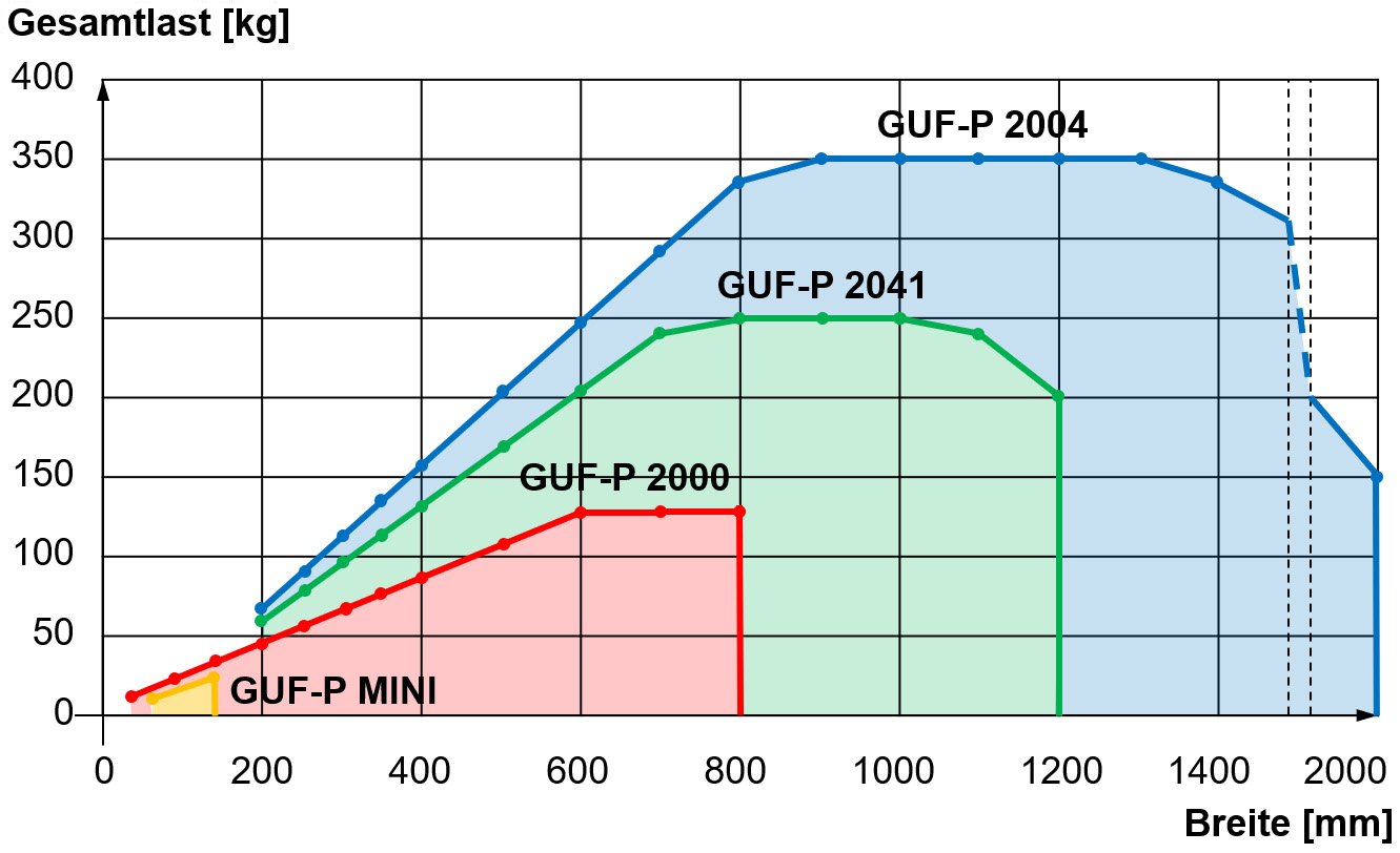
System selection based on load and conveyor width
The following diagram can be used as a basis for determining the permissible total load based on the conveyor width of each conveyor system. The values included apply to the max. tail diameter per system and a belt with a strength K1% of 5 to 8 N/mm.
Yes, belt conveyors from mk are available without increments in every length and width of the specified range. However, to ensure that the belt runs safely and stably, attention must be paid to the correct length-to-width ratio (see question 6). In individual cases, we ensure that the maximum widths and lengths as well as the ideal length-to-width ratio are exceeded by taking appropriate design measures.
For easy and quick belt conveyor delivery, however, we recommend selecting the conveyor width from the respective available range. The use of standard components can avoid lengthy and costly special constructions.
To ensure secure and stable tracking, the belt conveyor should have an ideal length-to-width ratio. Outside of this ratio, the regulating effect of the round roller for automatic belt adjustment cannot be utilized.
A stable range without restrictions has a ratio of length to width from 2:1 to 20:1 (i.e. from twice as long as wide, to 20 times as long as wide).
Likewise, a range from 1.5:1 to 2:1 is also usually possible without restrictions, but requires a design test. The range of 1:1 to 1.5:1 is only possible with restrictions and with additional design measures such as lengthwise fences.
In the range of 20:1 to 50:1, only laterally stiff belts must be used; in addition, transverse forces are no longer permissible. They occur, for example, when there is lateral movement, lateral product discharge, lateral product transfer, lateral product alignment using a side rail and asymmetric load distribution.
Yes, the horizontal material flow around curves can be realised with a curve belt conveyor. This is a stand-alone conveyor module. In combination with straight and bent routes, a continuous and uninterrupted concatenation is guaranteed. The transported goods are guided without contact and retain their orientation.
The KGF-P 2040 curved belt conveyoris available in designs with 90° and 180° and in widths from 300 to 600 mm. It is also equipped with a rolling knife edge with ø 20 mm (see question 19), so that even small products can be transferred reliably to the next system.
Alternatives from mk
In a continuous chain, in which the conveyed goods can be guided with contact, e.g. lateral guides, switches or pushers are used. With these, a product can be transferred from one conveyor to another conveyor, placed at right angles to it.
If the constant flow of the chain can be interrupted, the change of direction can also be effected, for example, by a rotary lifting unit. This takes the product from conveyor 1, turns in the conveying direction of conveyor 2 and transfers the product to it.
Yes, you can use belt conveyors to transport products to other levels as well. Inclines and descents of up to approx. 20° are typically possible with straight belt conveyors. It depends on the belt selected, product weight and drive performance.
Incline conveyors (also referred to as Z-conveyors) are used for inclines exceeding 20° and, especially, for incline conveying for small parts. The incline conveyor KFG-P 2000 was constructed for this purpose and is based on the belt conveyor GUF-P 2000. The incline angle is variable, and various belts, cleats, stands, funnels, slides and side rails can be selected. Equipped with rollers for mobility, this series is particularly well-suited for mobile use in filling containers or lattice boxes.
The KFG-P 2000 ECO is a design of the KFG-P 2000 series restricted to 18 different versions. ECO stands for economical, meaning an optimised cost/benefit ratio, which is reflected in the conveyor’s affordable price and quick delivery times.
Alternatives from mk
If the goods have to be transported to another level in a continuous, uninterrupted chain to save as much space as possible, spiral conveyors are also available. Ideally, these are realized with flat top chain conveyor systems such as the Versaflex or SBF-P. Depending on the application and the structural design, these also serve as buffers in most cases.
If the linking can also be discontinuous, the use of a lift system is recommended for the vertical transport of pallets or workpiece carriers. The implementation takes place with workpiece carrier systems such as the Versamove.
The belt conveyor's transport medium is the conveyor belt. The continuous belt is moved over two pulleys via friction closure: the drive and idler pulley. The drive pulley is motorised via a head drive, lower belt drive, or internal drive.
When head and lower belt drives are used, the force is transferred directly through the shaft or indirectly via the chain or timing belt. The benefit of indirect drives is the option of lift-and-transfer, fine increments in speed, and the possibility of subdued start-up.
The head drive, including the motor, can be positioned on the inlet or discharge end, above or below the conveyor frame, and to the left or right. A motor orientation of 0°, 90°, 180° or 270° can be selected.
The lower belt or middle drive is arranged under the transport layer using snub rollers. Conveyors with lower belt drives have the advantage of conditional reversible operation and the option of knife edges (see question 19) on the inlet and discharge end.
Drum motors are used for internal drives, and the conveyors manifest no interfering contours as a result. Therefore, they are optimally suited for integration into systems with little installation space.
Yes, you can drive several conveyors synchronously with one motor.
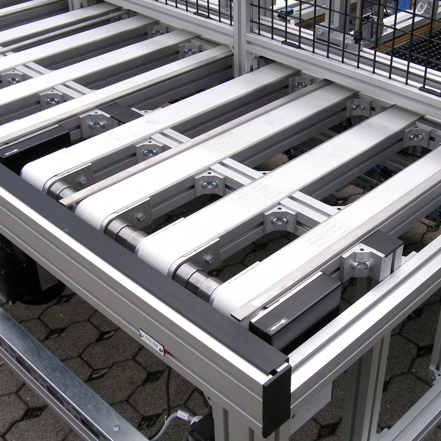
With lines running in parallel, a belt conveyor with head drive (AC and AF) can be coupled with any number of belt conveyors without own drive (AA). The journals of the aligned drive rollers are simply connected with couplings for this purpose.
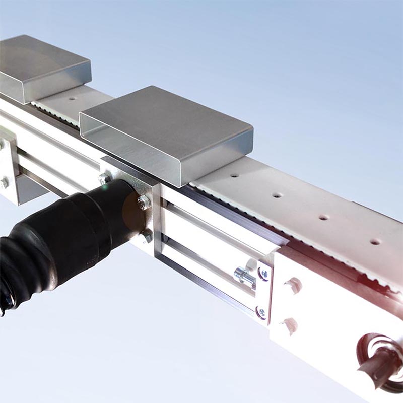
Such a coupling can, of course, also be carried out with underbelt drives (BC with BA). This is useful, for example, if the distances between the conveyors have to be adjustable. In this case, the inner conveyor lines are mounted on guide rods or guided by a linear unit, see photo below.
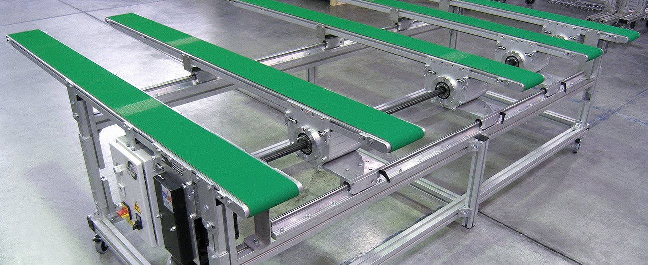
For belt conveyors that are located behind or above one another, the drive can be created using chains or timing belts.
Yes, belt conveyors can be turned on and off as necessary, for example, to load or remove parts. During continuous operation, conveyors run uninterrupted. The goods to be conveyed are fed onto the running conveyor.
If there are up to four shutdowns per minute, this is referred to as on/off operation. We also always recommend this to reduce wear if it is foreseeable that no action will occur for more than 30 seconds.
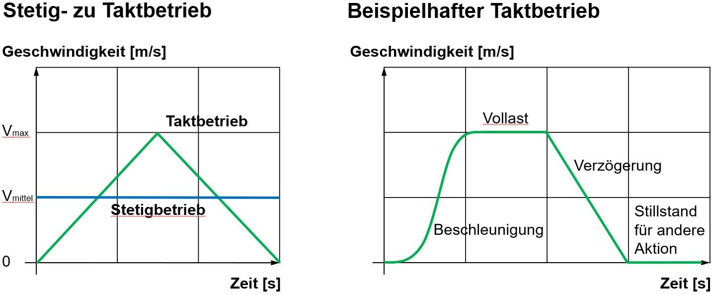
As a rule, cycle operation is a fixed cycle that is repeated. If there are more than 30 cycles per minute, servo drives are usually required. Rates of more than 60 cycles per minute are available on request, but they require a detailed assessment of the application.
The specification of the repeatability and positioning accuracy to be achieved is important for cycle operation. Positioning accuracy in a range of ± 10 mm is possible with simple devices, such as initiators or light barriers. As a rule, the range of ± 5 mm requires a positive-locking drive and control with signal transducers. The range of ± 1 mm represents the transition to the linear technology.
The diagrams show the need for a higher maximum speed in cycle operation compared to continuous operation. In addition, they show an example of the course of a cycling operation with soft start-up and standstill for a different action (e.g. to process the conveyed product).
Yes, conveyed goods can be accumulated on a belt conveyor.
During accumulated operation, the conveyor continues to run below the accumulated product. This can continue for longer or shorter periods of time (for example, when moving against an end stop, when there are slight changes in speed from one conveyor to the next or when moving light loads crosswise).
Depending on the total load and speed, the motor power may need to be twice as high because the friction value in accumulated operation may double in comparison to continuous operation. However, this must be assessed in detail based on the specific application scenario. How much weight is actually accumulated? What is the friction value of the product to be accumulated?

In general, you must determine whether the conveyor belt used is suitable for “accumulated operation”, “conditional accumulated operation” or “non-accumulated operation” (see question 16) for the application in question.
High-quality motors and gearboxes from SEW-EURODRIVE are used as standard. These gearmotors consist of an asynchronous AC motor or a DC motor combined with a Spiroplan, helical-worm or helical gearbox. Their efficiency class is IE3 and degree of protection is IP 54. Custom motors, servomotors, UL-CSA approval and multi-range motors can also be used as options.
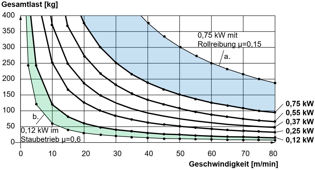
Selecting motors based on speed and load
The diagram below can be used to determine the motor power required based on the total load (conveyed material + medium of transport) and the speed. The values shown correspond to a kinetic friction value of μ=0.3, which is the friction between the belt and the slide bed in a belt conveyor.
Example of the influence on the permissible total load and speed, if...
a. ...the friction value is halved from a belt conveyor (µ=0.3) to a roller conveyor (µ=0.15)
b. ...the friction value doubles from continuous operation (µ=0.3) to accumulated operation (µ=0.6)
These values serve as rough guide values and must be assessed in more detail based on the specific application. What size and type of tail is used? Is a knife edge required? Does the product need to be accumulated? What is the friction value? An exact value is reached through a detailed motor calculation. In the majority of the calculations, the motor power required is actually lower than expected.
A nominal speed within the specified range can be selected. The maximum conveying speed depends on the motor selected, the load on the belt, the operating mode and other factors. The speeds provided here are nominal values and may deviate due to the speed tolerances of the motors (from -10% to +20%). Higher speeds are also achieved when the system is operated on a 60 Hz grid (for example, in the USA).
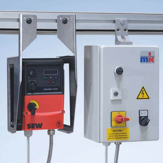
If you need precisely defined speeds, this can be accomplished with a frequency inverter or mk reglomat.
mk reglomat for DC motor
For direct current, the reglomat can be used to control the speed within a range of 1:6 (0.25–1.5 A or 0.5–3 A).
Frequency inverter (FI) for three-phase motor
The frequency inverter allows you to control the conveyor speed within a range of 1:7 (10–70 Hz), assuming an alternating current and the nominal speed at 50 Hz.
For an even larger adjustment range (of 1:100, for example), it is possible to use servo motors on request.
You can use a rubber-coated driving roll when you want a belt conveyor to achieve maximum acceleration, particularly in damp conditions. This ensures that the torque of the motor can be transferred to the belt in the optimum way and without slipping. For example, a rubber-coated driving roll is usually required to use a stationary knife edge (see question 19). The disadvantage of this solution, however, is that it causes increased wear.
During use, the belts in conveyor belt systems are subjected to permanent stress by the conveyed goods and environmental conditions. Choosing a suitable conveyor belt is therefore of great importance and depends on a large number of parameters.
Is accumulated, conditional accumulated or non-accumulated operation required?
Is the application suitable for a knife edge, antistatic or FDA-compliant?
Oil-resistant, cut-resistant or temperature-resistant?
Textured, printed or transparent?
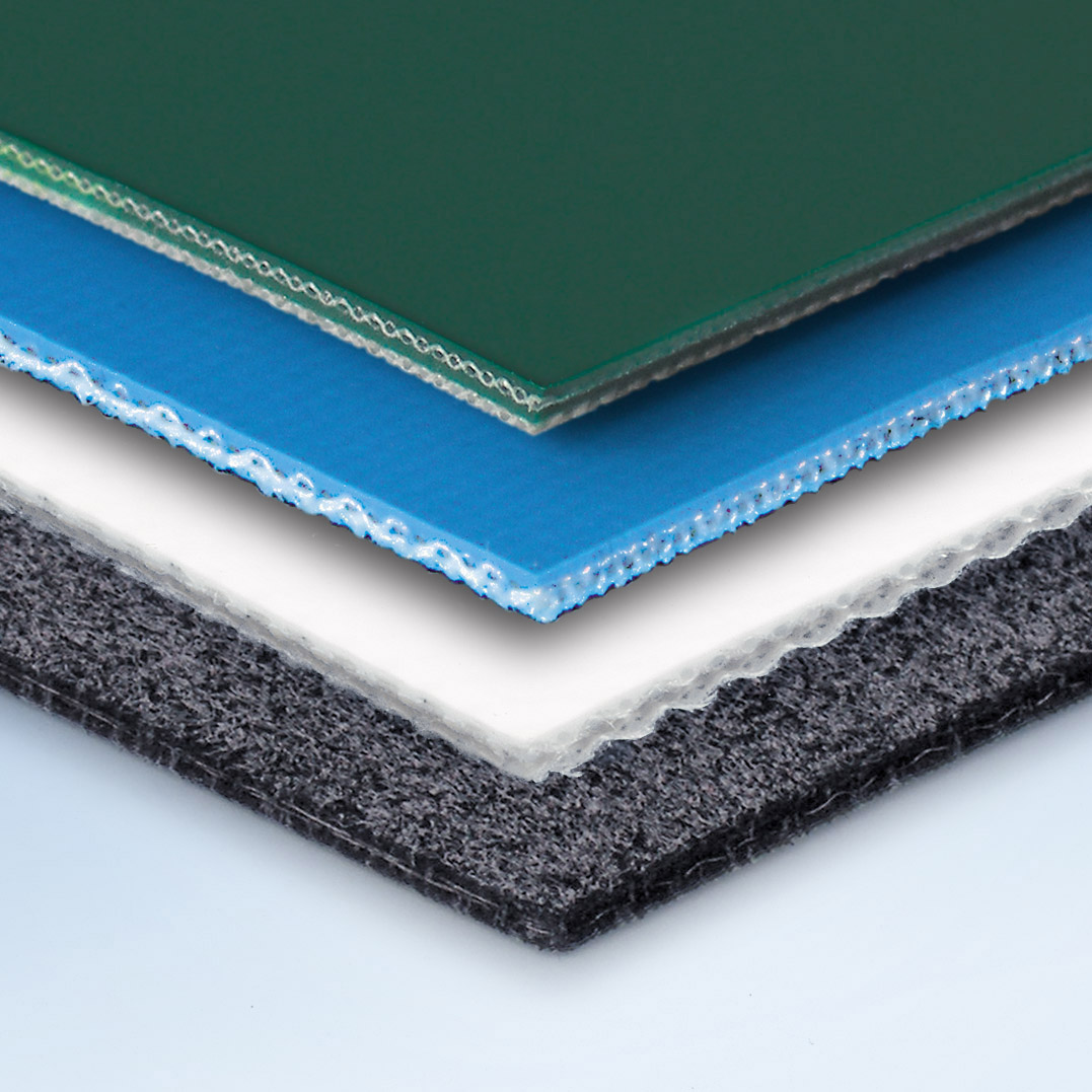
PVC, PU or Novo?
mk’s range of standard conveyor belt types offers a wide selection of materials and structures for virtually every conveyor application.
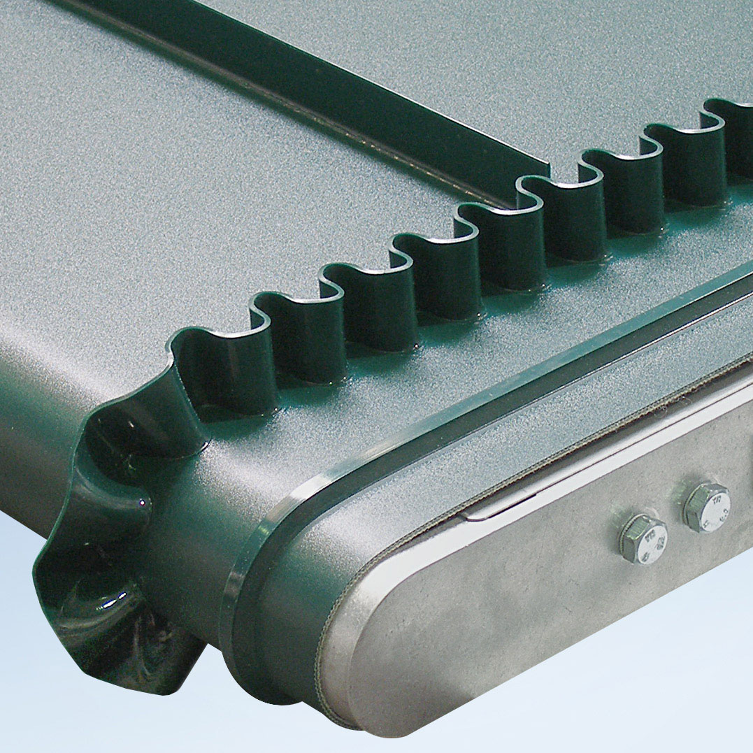
Depending on the conveying requirements, the conveyor belt can also be equipped with weld-on profiles, such as cleats or side walls. Side walls are used, for example, as a lateral boundary for increasing the loading height of the belt conveyor. Cleats are used to carry the conveyed material on continuous conveyors or to separate the belt (see question 17).
Yes, you can define and separate areas on a conveyor belt.
For example, if you need to sort the products on a belt conveyor (that is, by feeding them in in a specific sequence) or convey collections of items, the conveyor belt can be fitted with partitions and markings.
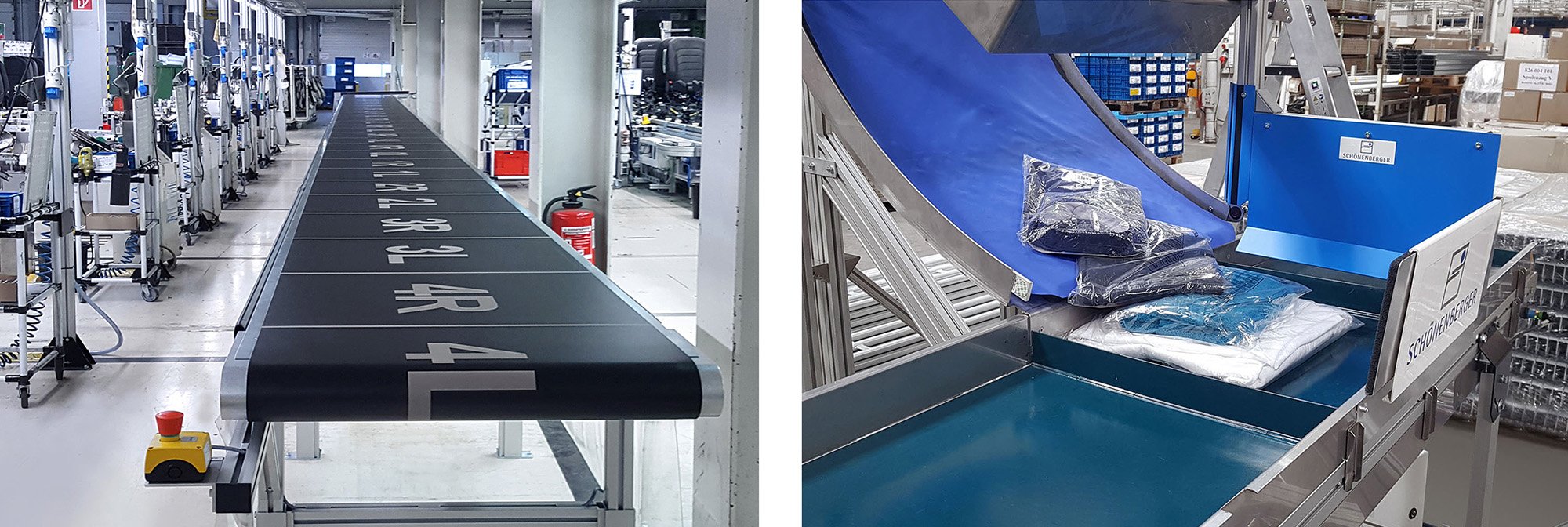
This can be done by printing lines and numbers on the belt, for instance. This allows you to place and process the conveyed material just-in-sequence (that is, according to the process sequence).
A belt can also be separated using weld-on profiles, such as transverse cleats. That makes it possible to create individual compartments where, for example, collections of items are gathered together, as is standard in mail order business. Combined with photoelectric sensors, the transverse cleats can also be used for timing the conveyor. Transverse cleats are mainly used, however, to carry conveyed materials on inclined conveyors, especially in combination with side walls for transporting bulk material (see question 18).
In the simplest case, the conveyed product is transported and removed from the conveyor again without any other contact. However, when products do need to be guided, the most commonly used solution is the side rail.
Side rails can simply be used along the sides of the conveyor to protect the product from falling or to prevent collisions with the surroundings. In this case, they are fixed in position, generally on the outer edge of the conveyor belt.
If the position, placement or orientation of the product needs to be manipulated, side rails can be used in many different ways. For example, they can be used to:
- Stabilise the product if it has a high centre of gravity.
- Centre the product on the conveyor belt.
- Divert the product in the conveying path.
- Feed in and discharge the product.
- Guide the product in multiple lanes.
- Rotate the product horizontally.
Side rails can either be fixed in position or can be designed in such a way that they can be adjusted according to the application. Where frequent format changes are required, the adjustment can also be carried out using linear guides with a handwheel and a counter or digital display. Automatic adjustment is possible on request.
Side rails can be mounted easily using the T-slot on the side of conveyor frame profile. Virtually all configurations are possible. Using the mk aluminium profile system gives your structure nearly limitless possibilities.
When transporting small parts and bulk product, there should not be a gap between the side rails and the conveyor belt. In this case, a side wall can be used as a boundary. This is a corrugated weld-on profile that is fixed lengthwise to the outer edges of the conveyor belt. It is used primarily on incline conveyors.
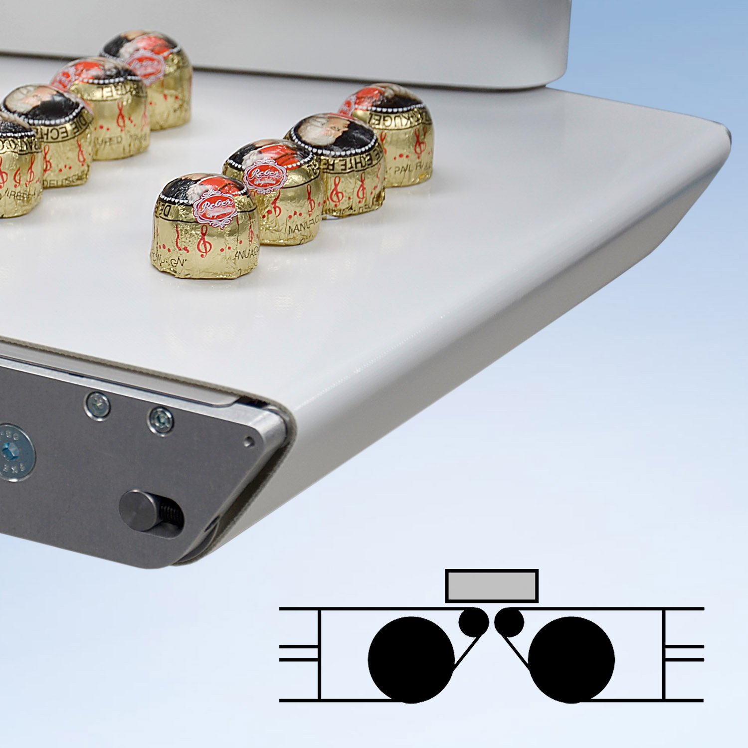
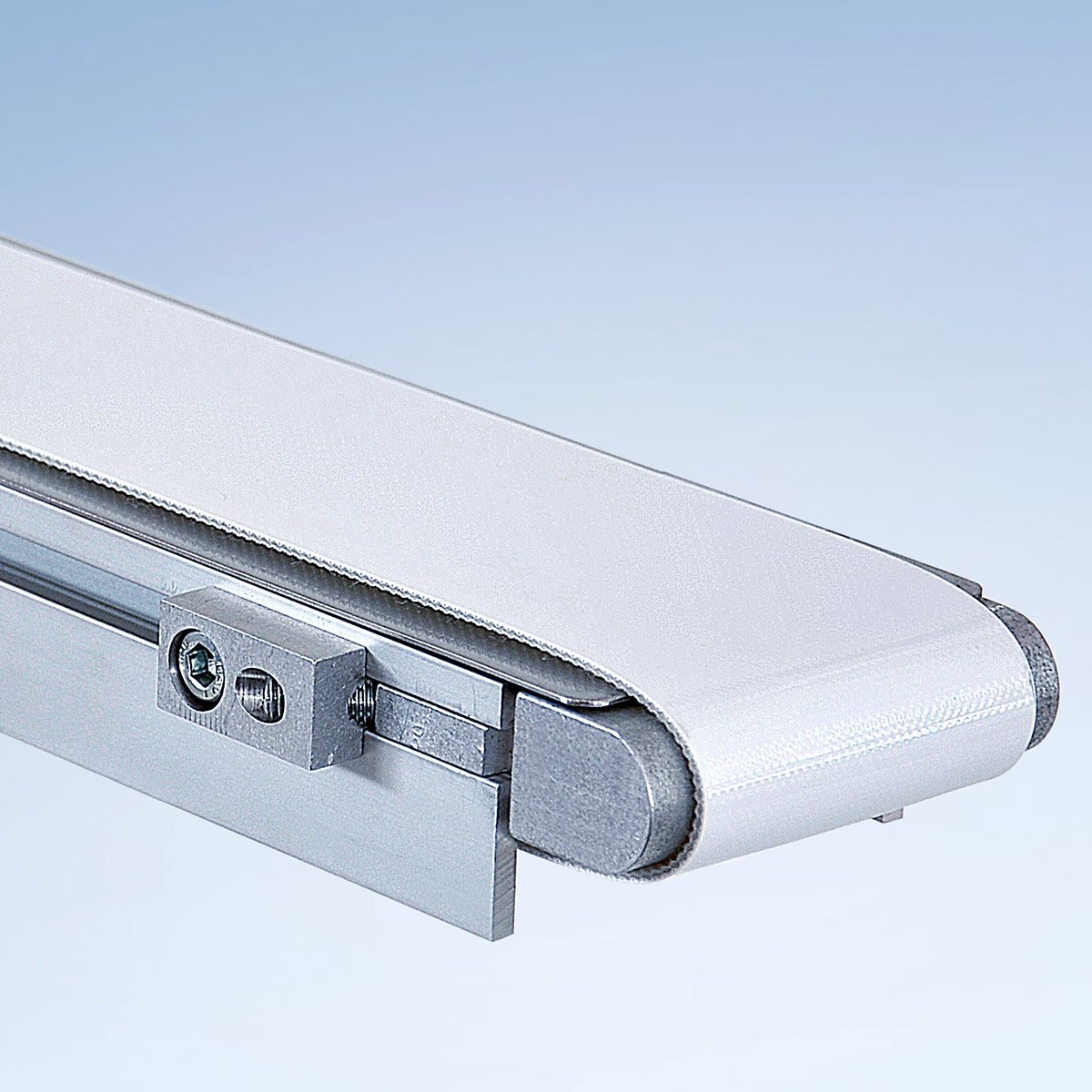
When transporting small products, it is important to keep the transfer from one belt conveyor to the other – for example, from a curve to a straight – as small as possible. As a rule of thumb for the safe transfer of products, they should be approximately three times as long as the distance from one contact point to the other. This can be realized using what is known as a knife edge. This may be an idler roller with a particularly small diameter (a rolling knife edge, ø 12/19 mm) or, in special cases, a fixed edge over which the conveyor belt slides (stationary knife edge, ø 10 mm). When selecting the belt, the minimum permitted diameter of the tail must be observed.
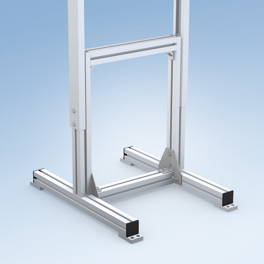
A secure and stable base is an essential requirement for a properly functioning conveyor. The way in which the belt conveyor is secured must be appropriate for the particular application. Different types of stands are available in a range of designs and weight classes, meaning there are virtually no limitations:
- Compact single stands for short and narrow conveyors
- Stable H-shape stands with horizontal braces and/or base cross-bars for extra stability
- Stands with fixed or swivel casters for mobile use
- Height adjustable and swivelling for changing process conditions
- Custom-built frames for special circumstances
- Direct connection to the machine frame using the T-slot on the conveyor frame
mk stand systems can be custom-configured and adapted to suit all applications and environmental conditions. Using the mk aluminium profile system gives your structure nearly limitless possibilities. To ensure system stability, it is important to take into account the ratio of height to width, the centre of gravity of the load and other influences.
Small conveyors and belt conveyors with minimal obstructing contours are particularly suited to confined spaces.
We developed the GUF-P Mini Small Conveyor specifically for this purpose. Thanks to its minimal installation height of 35 mm, this series is ideal for use in complex systems where space is at a premium. Since the belt recirculation is integrated in the conveyor frame, the conveyor can even be placed directly on the machine bed. It is available in lengths of 360 to 5,000 mm and in belt widths of 75 to 150 mm.
Obstructing contours
For most applications, the compact height of the conveyor frame is a critical factor. Obstructing contours, such as the drive, may protrude and be a little larger, and will mostly be outside the relevant area of the machine.
However, if the drive really does cause an issue, there are many ways to position or proportion it differently. Our head drives (A*) and lower belt drives (B*) can be mounted on the conveyor in virtually any position. Stepper motors and servomotors with a high power density are also an option. They are considerably more compact than three-phase current asynchronous motors with large gearboxes.
If the entire conveyor is to be installed inside a machine, it will usually need to have few or no obstructing contours. In this case, we recommend an integrated motor, such as a drum drive (C*), which is available in diameters of 53 mm and 81 mm for the GUF-P 2000.
Drives for mk conveyor technology
Alternatives from mk
If you require a very narrow conveyor, you may sometimes find that, depending on the length of the conveyor or the surrounding conditions, the existing frictional connection is not sufficient for the drive due to a lack of friction surface. In this case, we would recommend a timing belt conveyor driven by positive mechanical engagement.
Yes, as well as simply transporting goods from A to B, belt conveyors can also separate, sort, arrange or buffer goods with the aid of simple equipment.
The easiest way to buffer or store goods is to move the products up to a stop (called an “end stop”) and then accumulate them on the belt conveyor (see question 12). In this case, the buffer area equates to the available belt surface area. This area can be increased accordingly using one or more parallel belt conveyors running in opposite directions. This reduces back pressure and prevents bridging. This type of buffering is ideal for tasks involving accumulation tables or tasks based on the first-in, first-out principle. For very small products that need the gap between the individual conveyors to be minimal, we recommend using flat top chain or modular belt conveyors. This “bi-flow” function allows you not only to buffer the conveyed goods, but also to separate and arrange them, letting you put them in an order suitable for automation.
Another option for separating and correcting the position of products is to use belt conveyors with different speeds. In this case, the conveyed good is transferred from a slow-running belt to a fast-running belt. This works for conveyors that are positioned in a row with or in parallel to each other. Conversely, if the products are transferred from a fast-running conveyor to a slow one, they are slowed down and the space between the products is reduced.
If you do not just need to separate conveyed goods but also to sort and discharge them, there are a variety of additional components you can use. They include, for instance, attachment parts such as stoppers, side rails, switches and star wheels. These parts let you process the products accurately at the required pace.
Alternatives from mk
Another common solution for the buffering, storage, positioning and separation of goods is a rotary table. This table is positioned between two work steps. The free space on the table is used as a storage area and the products can be discharged and fed back into the process if necessary.
To fulfil special requirements, additional functions can be integrated into the belt conveyors. That includes, for instance, back light units for optical inspection systems or vacuum conveyor frames for conveying goods in fixed positions. However, magnetic conveyors for ferromagnetic piece goods or scanning conveyors with integrated systems for reading and writing data (e.g. RFID) can also be provided. Unusual tasks require special solutions.
Yes, you can put the belt conveyor into operation yourself. The conveyor comes with instructions for mechanical setup in English and German.
The version of the conveyor with the controller (reglomat, frequency inverter) has the CE marking and fulfils the Machinery Directive requirements for completed machinery. In this case, it simply has to be connected to the power supply via a plug.
In the standard version, the motor is installed but not connected. The system can be delivered as “motor with terminal box”. In this case, the electrical installation must be performed by a specialist.
A crescent-shaped belt is a conveyor belt that has not been correctly assembled. It describes a bend along the length of the frame in the shape of a crescent. This defect occurs if the permissible manufacturing tolerances are not observed when cutting the width and if the connection to the continuous belt is not perpendicular. Crescent belts are less able to centre themselves due to the different regulating effects of the crowned roller. This defect is easily identified when the uninstalled belt is folded on top of itself. Our service technicians will be happy to assess this using a photo. If the belt is crescent-shaped, it must be replaced.
If you need help with a defect or a complaint, please contact our service team at service(at)mk-group.de.
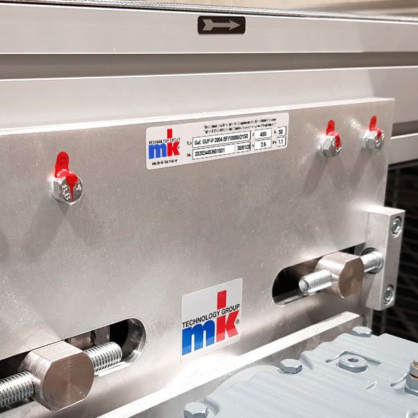
Tell us the machine number and/or take a picture of the mk rating plate (located on the conveyor drive) and briefly describe the issue.
The documentation that comes with the conveyor includes drawings and wear items. The parts required for a replacement can be identified in this documentation.
If the conveyor belt is worn out or defective, it must be replaced. Conveyors up to 600 mm in width can be replaced and welded directly on site. A mobile belt welding system ensures seamless connections of the highest quality.
Nearly all electronic, electrical and optoelectronic components are electrostatic discharge-sensitive components (ESDS). Effective ESD protection is required to protect the sensitive components against damage or destruction. This is described in the DIN EN 61340 Standards.
A standard ESD conveyor system from mk provides the following:
- Antistatic transport medium (conveyor belt) and wear strips with < 1011 Ohm surface resistance
- Conductive components such as “PE” nuts with < 105 Ohm surface resistance as ESD protection components
- Designed for dry environments (humidity >40% and < 60%) and room temperature 20°C
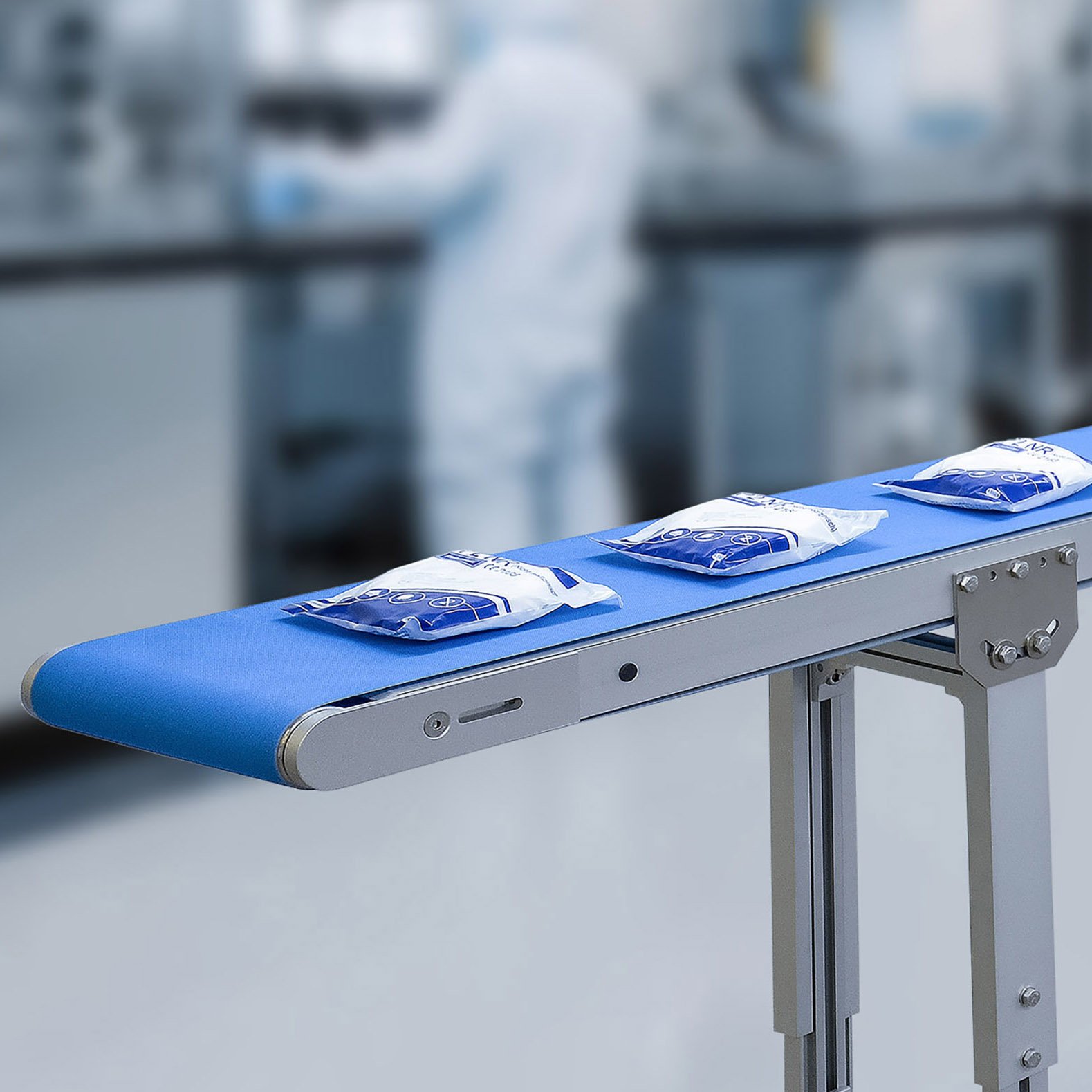
Yes, mk has the knowledge and expertise to design conveyors that are specially adapted for cleanrooms and laboratories. These cleanroom belt conveyors and timing belt conveyors are designed to ensure low particle emissions and optimised cleaning. They are particularly suitable for use in production environments with high requirements in terms of technical cleanliness, such as in micromechanics, the manufacture of electronic and optical devices and the production of batteries and fuel cells. Certification for the belt conveyors is available. Furthermore, they are produced in accordance with cleanroom requirements and can be delivered in sealed packaging for rapid deployment in the cleanroom.
As a rule, belt conveyors are very low-wear and low-maintenance. However, to avoid breakdowns, the belt conveyor should still be subjected to regular preventive maintenance. Ideally according to the intervals specified in the operating instructions. For safety reasons, however, maintenance may only be carried out by trained specialists. Non-professionals should contact the mk service team. Depending on customer requirements, individual maintenance contracts can also be agreed.
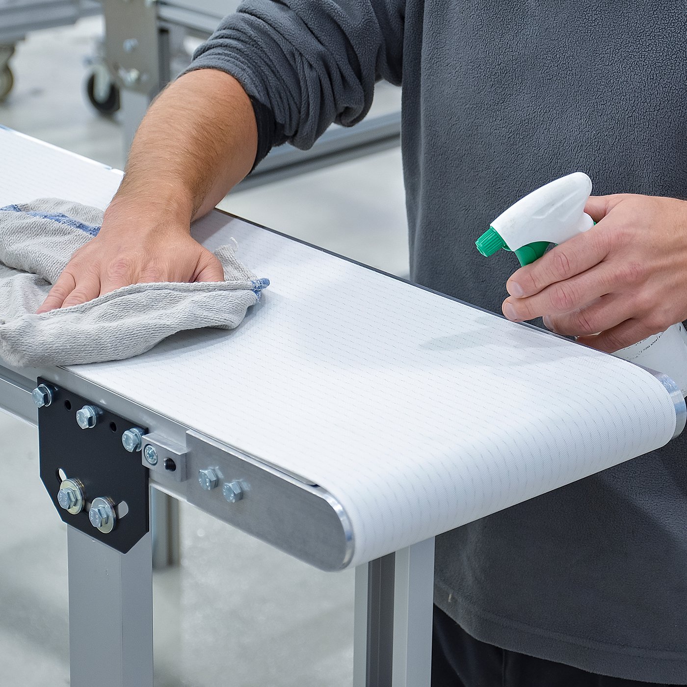
Cleanliness is crucial for fault-free operation of the conveyor. To guarantee continuous function and operational safety, non-professionals can perform a visual inspection and surface cleaning on the belt, the slide bed and other freely accessible assemblies. Depending on the belt, different cleaning methods must be used (smooth belt: damp cloth, felt belt: suction device). In order to avoid injuries, the conveyor should be disconnected from the mains beforehand.
Go to technical service department
The belt is tensioned and adjusted at the factory before the delivery of the conveyor. If your conveyor belt does not stay on track, i.e. if the belt becomes misaligned, the following points should be checked:
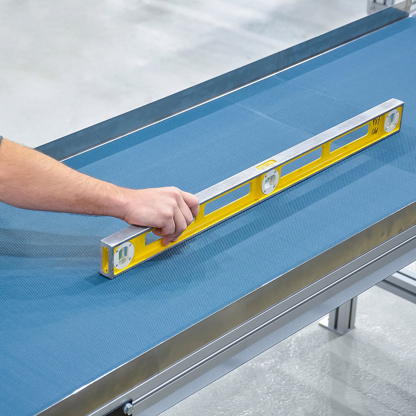
- The conveyor frame must not be twisted, i.e. distorted during installation. The conveyor must be perfectly flat and checked with a spirit level lengthwise and crosswise.
- All rollers must be clean. Damaged or severely worn parts must be replaced.
- All rollers (drive, tail, and, if necessary, lower belt rollers) must be paraxial and at a right angle to the tracking.
- The pre-tension should only be as high as necessary for the correct synchronisation of the belt under a load.
Due to transport, installation or belt slackening in the first two weeks after commissioning, it may need to be retensioned or readjusted. Since the conveyor belt is also subjected to high loads, it will lengthen over time. It must therefore be tightened at set intervals. The track must also be adjusted.
For safety reasons, however, maintenance may only be carried out by trained specialists. Non-professionals should contact the mk service team. Depending on customer requirements, individual maintenance contracts can also be agreed.
Go to technical service department
Crowned (cylindrical and conical) rollers
As with all mk belt conveyors, the crowned design of the drive and idler rollers make belt adjustment significantly easier. The roundness ensures that the belt runs centrally on the conveyor frame. Due to the different circumferential speeds of the roller, the belt strives for a balance of forces between the left and right conical area. Self-adjusting belts require the correct pre-tensioning of the belt and, depending on the type of belt, a length-to-width ratio of 2:1 to 20:1. Swinging of the belt is perfectly normal. The belt requires 2 to 10 revolutions to utilise the regulating effect of the crowned roller. The belt is always slightly narrower than the conveyor. Light contact with the edge of the conveyor frame or connecting elements such as belt supports or side rails rarely causes major problems.


